Electricity
Work through one section at a time. Higher-only material is labelled explicitly; optional challenges can also use Foundation content.
 GCSE PHYSICS · AQA TRILOGYTutor dashboardSaves on this device
Your answers save automatically as you work.
Saved in this browser on this device.
Follow charge through circuits, explain how components behave, and calculate the energy transferred by electrical appliances. Includes both required practicals and clearly labelled Higher-only transformer calculations.
Supported GCSE version · Clear examples, worked calculations and optional challenges.
Work through one section at a time. Higher-only material is labelled explicitly; optional challenges can also use Foundation content.
An electrical property carried by particles; charge flow is measured in coulombs.
Charge flowing past a point each second, measured in amperes.
Energy transferred per coulomb of charge between two points, measured in volts.
How much a component opposes electric current, measured in ohms.
A conductor whose current is proportional to potential difference at constant temperature.
Components connected one after another in the same path.
Components connected in separate branches between the same two junctions.
A resistor whose resistance changes with temperature; here resistance decreases as temperature rises.
Light-dependent resistor; its resistance decreases as light intensity increases.
A component that carries current mainly in one direction.
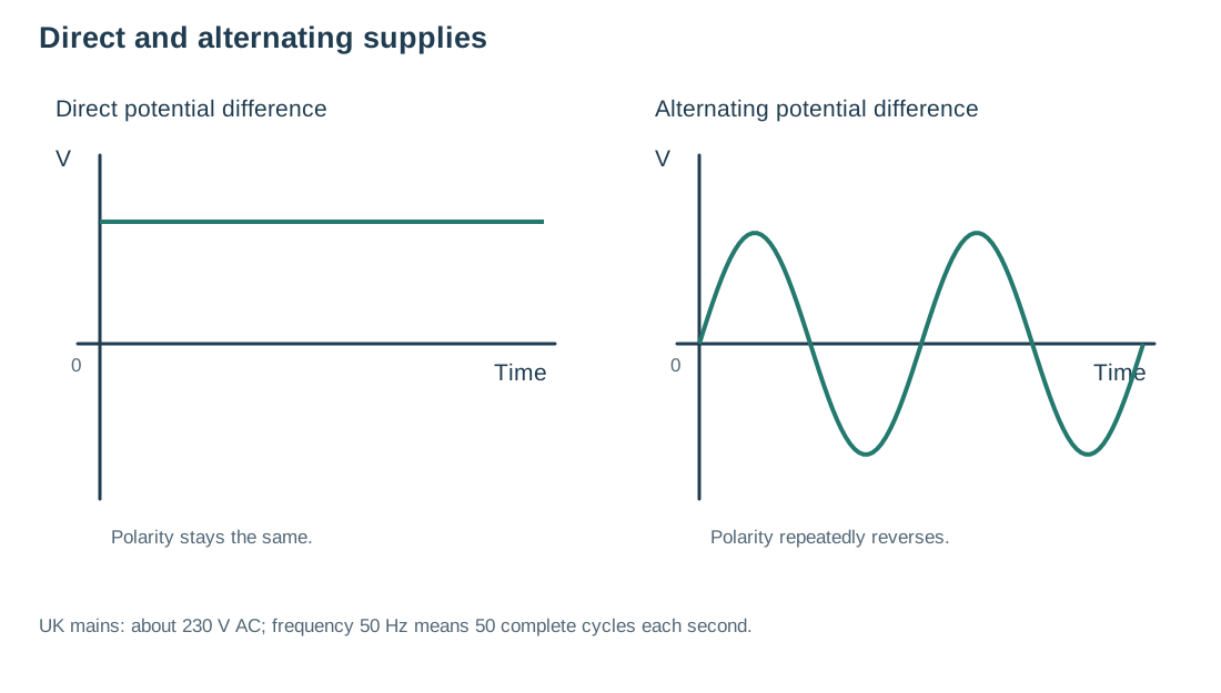
A potential difference whose polarity stays the same.
A potential difference whose polarity repeatedly reverses.
Energy transferred each second, measured in watts.
A safety connection that can carry fault current from an exposed metal case.
A device used with AC to increase or decrease potential difference.
The resistance of one resistor that could replace a combination with the same overall V–I behaviour.
A current is moving electric charge. In a metal wire, electrons already present in the metal move through the circuit. A cell or battery supplies a potential difference that transfers energy as charge moves. A working circuit needs a complete conducting path and a source of potential difference.
Current tells us how much charge passes a point each second. A current of 1 ampere means 1 coulomb of charge passes each second. In one unbranched loop, the current is the same everywhere: charge is not used up by a lamp. Energy is transferred by the lamp.
A torch carries 0.25 A for 2 minutes. Time = 2 × 60 = 120 s. Q = 0.25 × 120 = 30 C.
Closing the switch completes the circuit. At fixed resistance, increasing potential difference increases current. The dots represent electron drift through the external circuit.
Model limitations: Electron motion is greatly simplified and not to scale. Conventional current is opposite to electron flow. The resistor is treated as having constant resistance and the wires as having negligible resistance.
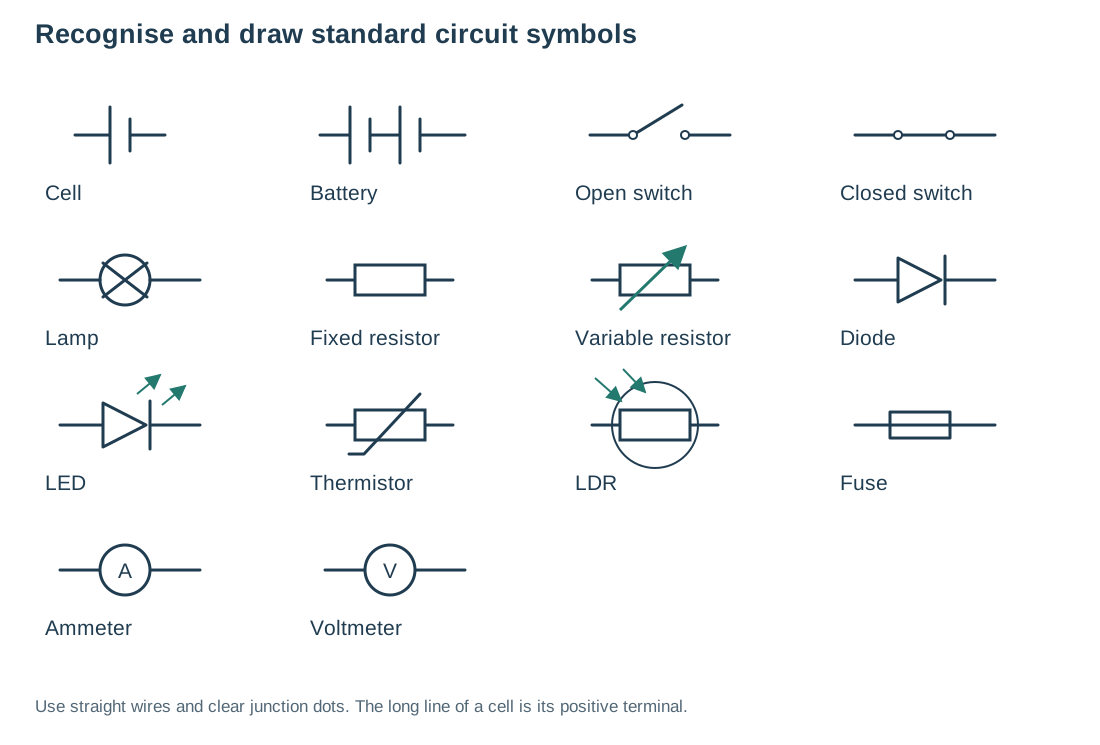
A circuit diagram shows connections using agreed symbols. It does not show the physical shape of the apparatus. Wires meeting at a junction are electrically connected; use a dot to make this clear.
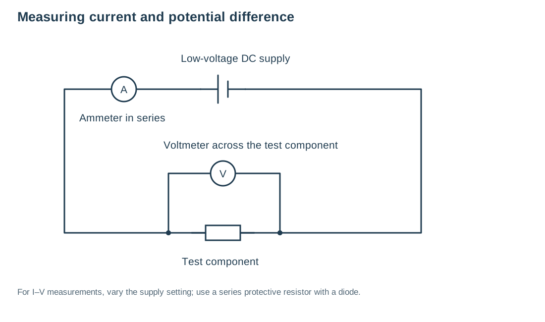
An ammeter goes in series so the current through the component passes through it. A voltmeter goes in parallel across the two ends of a component to measure potential difference.
Model limitations: These are circuit schematics, not physical layouts. They show ideal meters and omit lead resistance and the small effect real meters can have on a circuit.
Potential difference is energy transferred per unit charge between two points. A potential difference of 6 V means 6 J is transferred for each coulomb of charge. Resistance describes how much a component opposes current. At the same potential difference, a greater resistance gives a smaller current.
A resistor has 6.0 V across it and carries 0.30 A. R = 6.0 ÷ 0.30 = 20 Ω. If its resistance stays constant, 12 V would produce 0.60 A.
For a metal wire, a longer wire has a higher resistance when its material, thickness and temperature stay the same. Temperature must be controlled because heating changes resistance.
Heating a metal makes its ions vibrate more. This increases electron scattering and reduces their overall drift for the same potential difference, so resistance increases.
Model limitations: This shows heating a metal, not every cause of resistance. Electrons do not move like visible balls, and their random motion is much faster than their net drift. Ions vibrate about fixed positions; they do not travel along the wire.
This practical has two parts: investigate wire length at constant temperature, and investigate resistors connected in series and parallel.
Expected results: resistance increases with wire length. Series resistance is greater than either resistor alone. Parallel resistance is less than either resistor alone. You do not need the reciprocal-resistance formula for this course.
An ohmic conductor has a constant resistance if its temperature remains constant. Doubling potential difference doubles current. Its I–V graph is a straight line through the origin.
A filament lamp is non-ohmic. More current heats the filament. The hotter filament has a greater resistance, so current increases less rapidly as potential difference rises. Its I–V graph becomes less steep at larger positive or negative potential differences.
A diode carries substantial current only in its forward direction. In reverse it has a very high resistance, so the current is extremely small. The simplified GCSE description is that it allows current in one direction only.
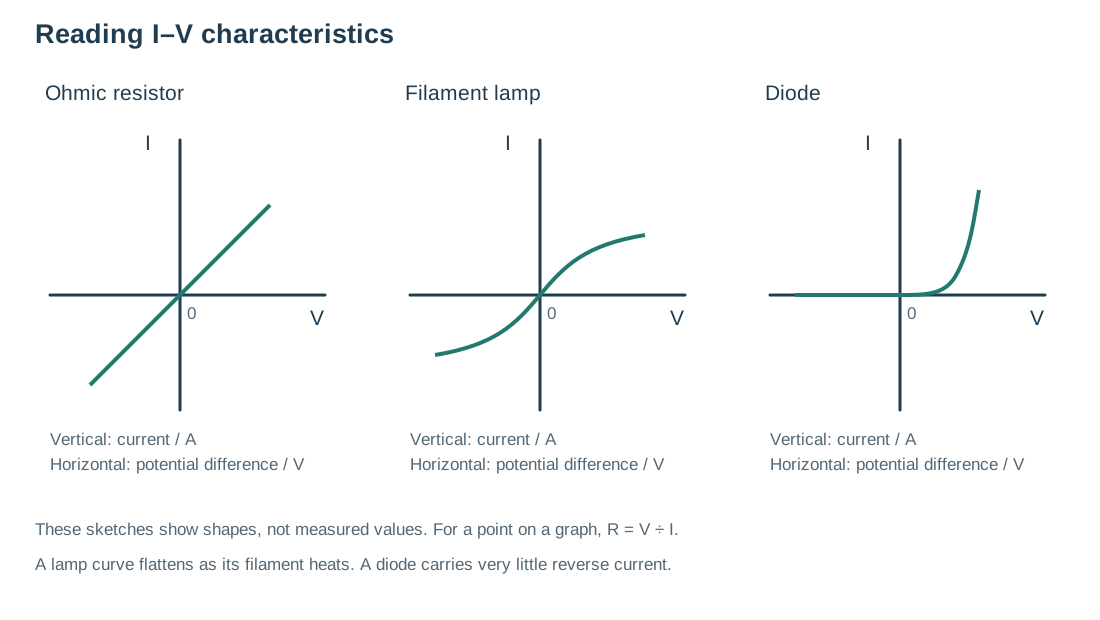
On an I-against-V graph, a steeper straight line through the origin means a larger current for a given voltage, therefore a lower resistance. A straight line that does not pass through the origin is not evidence of direct proportionality.
A thermistor is a temperature-sensitive resistor. For the type studied here, its resistance decreases as temperature increases. A thermostat can use the resulting circuit change to detect that a room or appliance has reached a set temperature.
A light-dependent resistor (LDR) has a lower resistance in brighter light and a higher resistance in darkness. A control circuit can use this change to switch a streetlight on when it becomes dark.
To investigate a thermistor, vary its temperature using controlled water baths and measure resistance at each temperature. Allow it to reach the water temperature and keep electrical connections dry. For an LDR, vary illumination while controlling other conditions; shade it or change lamp distance, without heating it. Compare resistance values or plot a graph. The sensor detects a change; the full control circuit decides what to switch.
Keep the fixed resistor cool so that its temperature stays approximately constant. The filament lamp is different: its temperature change is part of the effect being investigated. Take repeat readings and investigate unexpected values rather than drawing a line through every point.
Components in series share one path. The current is the same through each. The supply potential difference is shared between them. Their resistances add: Rtotal = R₁ + R₂.
Adding another resistor in series increases total resistance. At the same supply potential difference, the current decreases. If one connection breaks, the entire loop is open and all components stop conducting.
A 4 Ω resistor and an 8 Ω resistor are connected in series to 6 V. Total resistance = 4 + 8 = 12 Ω. Current = 6 ÷ 12 = 0.50 A. Across 4 Ω: V = 0.50 × 4 = 2 V. Across 8 Ω: V = 0.50 × 8 = 4 V. Check: 2 + 4 = 6 V.
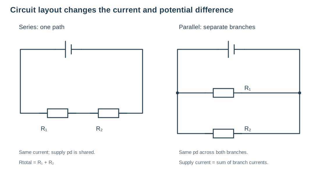
Parallel circuits have separate branches. Each branch has the same potential difference as the supply across those junctions. Supply current equals the sum of the branch currents.
Adding a parallel resistor provides another conducting path. For the same supply potential difference, more total current can flow, so total resistance decreases. It is lower than the resistance of the smallest individual resistor.
A supply current of 1.20 A splits into two branches. One branch carries 0.45 A, so the other carries 1.20 − 0.45 = 0.75 A. Both branches have the full supply potential difference across them.
Domestic appliances are connected in parallel so each receives the intended supply potential difference and can be controlled independently. Opening one branch does not break the other branches.
Identical lamps in series share the supply potential difference. In parallel, each lamp has the full supply. Opening one parallel branch leaves the other branch complete.
Model limitations: The lamps are idealised and brightness is illustrative. Real filament resistance changes with temperature. Moving dots simplify charge flow and do not show the speed at which energy is transferred.
A cell or battery provides a direct potential difference: its polarity remains the same. In a simple resistor circuit this produces current in one direction. An alternating potential difference repeatedly reverses polarity, producing current that repeatedly reverses direction.
In the UK, mains electricity is approximately 230 V AC at 50 Hz. The frequency means 50 complete cycles each second, not 50 coulombs each second.
| Wire | Insulation colour | Role |
|---|---|---|
| Live | Brown | Carries the alternating potential difference from the supply. |
| Neutral | Blue | Completes the normal circuit; at or near 0 V relative to Earth. |
| Earth | Green and yellow stripes | Safety connection to an exposed metal case; normally carries no current. |
A live wire has about 230 V potential difference relative to Earth. A person connecting live to Earth can form a conducting path and receive a dangerous electric shock. An open switch does not guarantee that every wire in an appliance is safe: the live wire on the supply side can still be live.
If a fault connects live to an earthed metal case, a large fault current can flow through the low-resistance earth path. A suitable fuse melts or a circuit breaker opens the circuit. A fuse is placed in the live connection so it disconnects the live supply. This is an explanation of protection, not an instruction to work on mains wiring.
Power is the rate of energy transfer. An appliance rated at 100 W transfers 100 J each second when operating at that rating. Power depends on the current through a device and the potential difference across it.
A motor draws 2.0 A at 12 V: P = 12 × 2.0 = 24 W. A resistor of 5 Ω carries 0.40 A: P = 0.40² × 5 = 0.16 × 5 = 0.80 W. To find current from power, rearrange P = VI to I = P ÷ V.
For a fixed resistance, doubling current makes heating power four times larger because current is squared. This matters in transmission cables and overloaded circuits.
Electrical appliances transfer energy into useful and less useful forms. A battery-powered fan transfers energy from the battery’s chemical store to the moving blades’ kinetic store, with energy also dissipated by heating and sound. A mains kettle transfers energy electrically to the thermal stores of water and the kettle, and some to the surroundings.
A 2.0 kW kettle runs for 90 s. First convert power: 2.0 kW = 2,000 W. E = 2,000 × 90 = 180,000 J. This is total electrical energy transferred, not necessarily all energy gained by the water.
Charge of 15 C passes through a 6 V lamp. E = 15 × 6 = 90 J. A larger potential difference means more energy transferred for each coulomb.
Higher power means faster energy transfer, but total energy also depends on time. A low-power appliance running for a long time can transfer more energy than a high-power appliance used briefly. Compare both quantities before deciding.
The National Grid links power stations and consumers using cables and transformers. Step-up transformers raise the potential difference for transmission. Step-down transformers reduce it before delivery to consumers.
For a given power transfer, increasing potential difference allows a smaller current because P = VI. Cable heating power is I²R, so reducing current greatly reduces energy dissipated in the cables. Transformers therefore help transfer energy efficiently over long distances. They do not create energy.
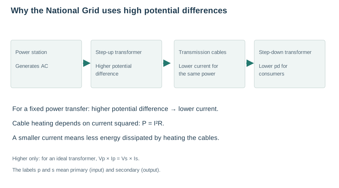
For an ideal transformer, or one treated as 100% efficient, input power equals output power: Vp × Ip = Vs × Is. Here p means primary (input) and s means secondary (output). Potential differences are in volts and currents in amperes.
A transformer has input 230 V and 0.20 A; its output is 12 V. Input power = 230 × 0.20 = 46 W. Output current = 46 ÷ 12 = 3.83 A (3 significant figures). A lower output potential difference allows a larger output current for the same power.
This equation is explicitly included in the current AQA 8464 Higher-tier National Grid content. The turns-ratio equation and detailed transformer construction are not required in this worksheet.
Start with the 44 main questions. Higher-only questions are labelled. You can complete this topic over several sessions; your answers save as you go. Use a hint if you get stuck, then compare your work with an example answer. Your tutor can mark written answers.
A student measures the same fixed resistor at several potential differences. The example results are below.
| Potential difference / V | 1.0 | 2.0 | 3.0 | 4.0 |
|---|---|---|---|---|
| Current / A | 0.10 | 0.20 | 0.30 | 0.40 |
Ammeter in series, voltmeter across the resistor. R = 1.0 ÷ 0.10 = 10 Ω; every pair gives the same result. Plot I vertically against V horizontally: a straight line through the origin. Keep temperature constant by using a low current and switching off between readings.
When connected with your pupil code, your answers save online for Kevin to see. Click Submit to Kevin when you have finished. Downloads are optional.
Connect with your pupil code above to submit.
Use a scientific idea and a specific example in your reflection.